 @Xavier@infosec.exchange
2026-06-07 01:05:00
I was answering a poll by @… and it reminded me about this amazing book about electronics that was written like a Captain Underpants book. I am curious if there are other #genX geeks that learned about
@Xavier@infosec.exchangeI was answering a poll by @… and it reminded me about this amazing book about electronics that was written like a Captain Underpants book. I am curious if there are other #genX geeks that learned about
 @sean@scoat.es
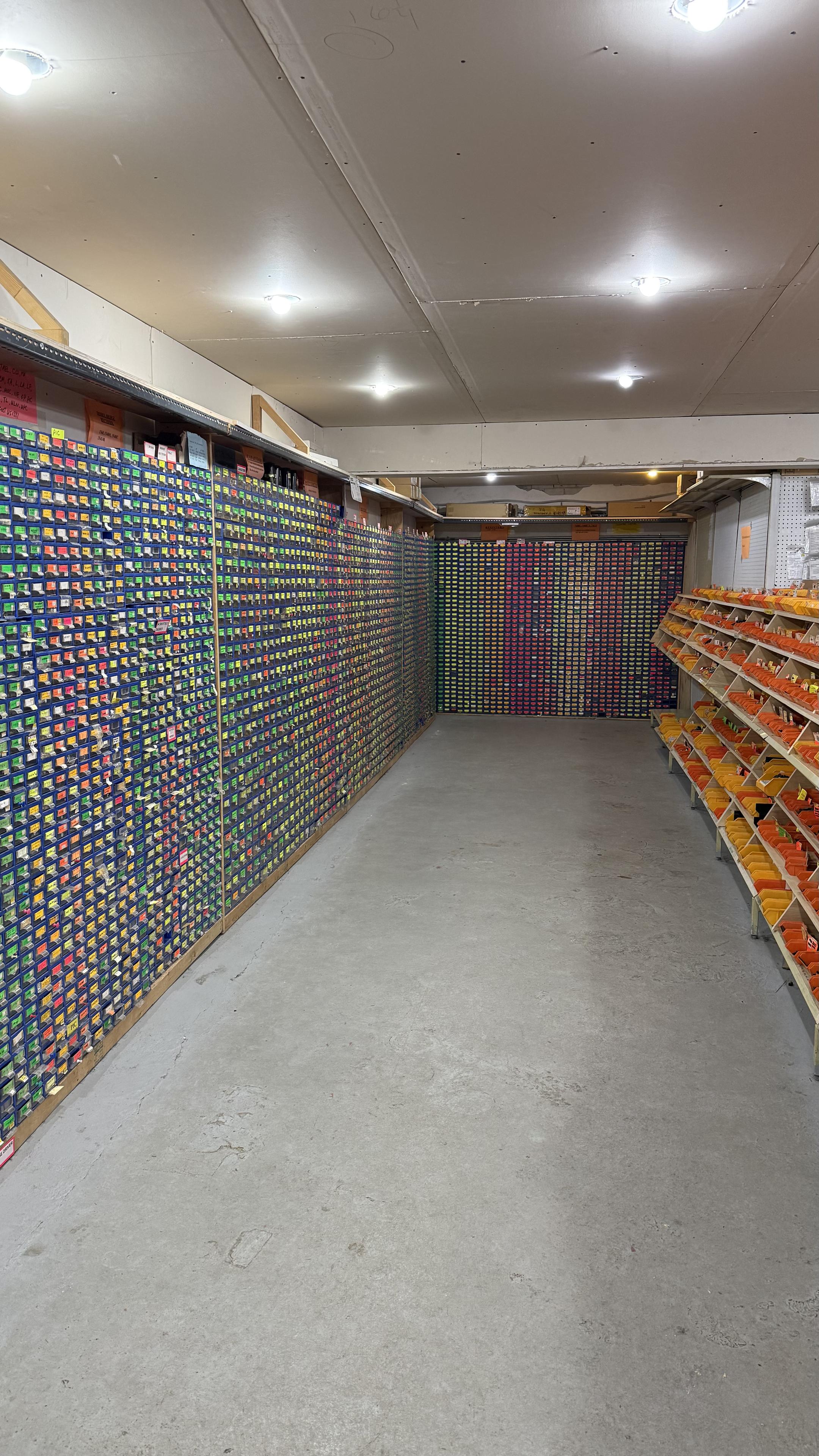
I was in #Toronto visiting the kid this weekend. Stopped by an #electronics store I had heard about, called "Supremetronic”…
Really, it was a section in the basement of a Home Hardware, directly next to the paint counter.
What a strange little nook of availability that was. Hundreds of bins o…
 @kineticdiplomacy@infosec.exchange
Testing batteries with a multimeter. I learned one thing after half an hour of no results: The multimeter is broken.
#diy #electronics